Introduction
Background
The increasing pollution of air by particles has made air cleaning a significant field in engineering and compelled developed countries to institute legislation that controls particulate emissions. Since most industries have particulate emissions, they employ complex and vigorous efforts in air cleaning process to protect their workers, the environment, and the entire population (Bredin 2012). A significant class of devices that control air pollution depends on the mechanism of filtering particle emissions from gas streams using fibrous filters. In this view, the employment of fibrous filters lacks an efficient alternative that can eliminate over 97% of particles ranging from 0.1μ to 1μ sizes from considerably varying rates of airflow.
Efficiency is an attribute that classifies fibrous filters into two categories of low efficiency and high efficiency. Fibrous filters with low efficiency have course fibers with diameters ranging from 100μm to 1000μm (Bredin, Larcher & Mullins 2011). These fibers are made of polymeric or metallic material. Usually, fibrous filters may effectively capture particles with the diameter of 2μm since smaller particles may penetrate due to a quick drop in inertia (Raynor & Leith 2000).
Comparatively, fibrous filters with high efficiency comprised of fine fibers that operate at slower airflow than that of low-efficiency fibrous filters (Agranovski 1995). Fine fibrous fibers that operate at a lower velocity have high efficiency (Bredin & Mullins 2012). Natural materials such as wool and synthetic materials create fibrous filters with high efficiency in collecting fine particles.
Low cost of manufacture and high efficiency of filtering are two advantages that make fibrous filters the most effective method of cleaning particles from a given airflow. According to Pohanish (2002), the removal of fine particles is critical for they penetrate the respiratory system and cause severe obstruction of alveoli. Empirical studies have established that long-term inhalation of particles has severe effects on respiratory and cardiovascular systems (Polichetti et al. 2009; Daz & Dominguez 2009; Binnig et al. 2011).
In industrial settings, legislation limits occupational exposure to particulate emissions. For instance, within an average period of 8 hours, while diesel soot has an exposure limit of 0.1 mg/m3, diesel engine lubricant has the same limit of 5 mg/m3 (Carstrol 2018). Thus, the particulate emission limit varies according to their respective sources.
Although numerous studies have extensively examined the filtration mechanism of solid particles, limited information is available on the effects that mediate the filtration process of colloidal aerosols such as liquid contaminated with soot and oil. Since these aerosols have contaminants, they have different properties from solid particles, and thus their filtration and the mechanism of the collection are comparatively complex (Jaganathan, Tafreshi & Pourdeyhimi 2009).
Liquid particles have lower filtration efficiency because they coalesce in fibers and form large droplets that migrate easily through filters, whereas solid particles have higher filtration efficiency because they form a filtration layer in the surface of the filter.
The mechanism of filtration is that when the filter attains a saturation level, the filtrate commences to drain out. At this level, it is feasible that the gas flow carries big droplets that coalesce at the base of the filter through the process of re-entrainment, which reduces the filtration efficacy of the filter (Stratakis & Stamatelos 2003; Agranovski 1995). Thus, the process of developing filters is difficult and complicated because of the heuristic procedures employed in their modeling. The production of surface filters in dust filtration is necessary to alleviate pressure drop and decrease flow resistance (Hilpert 2010). Since this process reduces downtime and the essence of regular disposal of utilized and contaminated filters, it is essential in extending the lifespan of filters and increasing benefits to both environment and air cleaning operations.
As filtration is a complicated process, numerous factors have varied direct effects on it. Filter structure, physical-chemical attributes of fiber, particle size distribution, the velocity of airflow, and physical parameters of the air stream are some of the factors, which have marked influence on the filtration process (Shahad 1989). At the formative stages of the theory of filtration, scientists have employed mathematical models to elucidate the mechanism of filtration and construct diverse forms of filters (Jakab & Omastova 2005). The analysis of the filter shows that it is a system of pores, capillary tubes, or a representation of a single fiber.
In the middle part of the 20th century (the 1930s, 1940s, and 1950s), a filtration model with a flow field coupled with an isolated cylinder placed perpendicular to the flow was a complex structure of the fibrous filter that was common.
Since 1959, when there was an elaborate resolution of the Navier-Stokes equations for series of cylinders placed vertically to the stream, the evolution of the filtration theory focused on getting accurate solutions to the issue of particle deposition on cylinders as in the case of fibrous filters (Happel 1959; Kuwabara 1959). Typically, the issue of particle deposition on new fibers comprises the significant realm of the classic theory of aerosol filtration.
The solution to this problem is the regeneration of clogged filters using various technologies, which remove solid particles trapped in filter membranes (Agranovski & Shapiro 2001). Researchers have made an elaborate explanation of the mechanisms and uses of various technologies to regenerate clogged filters (Theodore & Buonicore 1988; Flagan & Seinfeld 1988; Cheremisinoff 1993). Their work formed the basis of various researches, which have contributed to the improvement of fibrous filters.
Research Objectives
In this view, this work seeks to contribute to providing considerable and novel contributions to the body of knowledge in the field of filter systems. The study envisages that the development of valid and empirical filter test methods will offer more insights into the mechanisms of filtration processes, which are integral in improving the design and optimization approaches of fibrous fibers. On this basis, this work will focus on investigating the effects of solid contaminants on the efficiency of fibrous filters in an outdoor environment.
Additionally, the study will focus on incorporating scientific knowledge in the design and manufacture of effective and efficient equipment employed in air cleaning. As the deposition of solid particles is a major challenge in the filtration process, this study will aim to improve the lifespan of filters and enhance their operational and environmental benefits.
Literature Review
Filtration
The filtration process is usually the most effective method of eliminating liquid or solid particles from airflow systems with aerosol streams. The need for clean air in the manufacturing industries, automobile applications, and health sectors necessitates the use of filters. Examples of applications off filters are in the product processing plants, analytical sampling, gas cleaning, and respiratory protection (Hinds 1999).
However, the use of filters is disadvantageous because collected particles accumulate and clog pores on filters, resulting in increased resistance, decreased energy efficiency, and amplified operation costs. Therefore, the requirement of frequent cleaning or replacement of filters implies that companies can either reduce the filtration duration or incur extra operational costs (Brown 1993). Additionally, the use of filters has setbacks because the process of filter cleaning entails the application of friction on membranes, leading to a decline in the lifespan due to wear and tear.
Type of Filters
Depending on the nature of membranes, filters can be classified as surface filters and depth filters. While surface filters collect particles on their surfaces by accumulating them to form a thin layer that acts as an extra filter, depth filters collect particles in their matrix that forms the entire filter. In this perspective, it is critical to select a filter that is appropriate for aerosol properties such as chemical activity, particle concentration, viscosity, and aggregate phase.
As the first form of filters, granular filters comprise of a column packed with fine isometric granules manufactured from ceramic materials (packed bed filters) (Tien 1989). In the development of granular filters, fine isometric granules granular filters are glued together using heat to create a uniform intact matrix that acts as a filter. As granules are made from ceramic materials, they form an inert material that resists chemical reactions, tolerates high temperatures, and remains stable for an extended period despite adverse environmental effects (Contal et al. 2004). Owing to their properties, granular filters are standard in salt, gas, or water treatment applications.
Comparatively, membrane filters are a form of surface filters that have pore structures with smaller pore diameter and lower porosity than granular filters (Hinds 1999). Although their structured permits membrane filters to attain a high level of efficiency, it induces a stiff resistance to the rate of air, making them susceptible to clogging and hard to clean. In this case, membrane filters are not suitable for aerosol filtration (Zhao & Povitsky 2009).
Usually, cellulose esters complexed with plastics such as Teflon and metals make useful membrane filters. Researchers have extensively examined other properties of these membranes and elucidated their mechanisms of action (Gentry & Spurny 1978; Manton 1967). Due to their weakness of clogging and retention of liquids, membrane filters are not appropriate for the long-term collection of liquid aerosols.
As another form of filters, fibrous filters are unique for constitute a product of an array of fine fibers made from glass, cellulose, stainless steel, and plastics. Previously, fibrous filters that operate in high-temperature applications utilized asbestos, which poses significant health risks, resulting in its stoppage in the manufacturing industries (Li & Marshall 2007). Stainless steel and ceramic fibers have replaced asbestos because they are not only resistant to heat but also a wide range of chemicals (Peukert 1998; Ruiz et al. 2000).
Fibrous filters manufactured from stainless steel and ceramic materials offer high filtration efficiencies, which places them in the categories of HEPA and ULPA. The sizes of fibrous fibers vary in both thickness and length with less than 100μm diameter and randomization in the arrangement without intentional orientation (Wang, Kim & Pui 2008). The available commercially fibrous filters are reinforced by felting, knitting, or interlacing with thicker fibers.
During filtration, cake formed on the surface of collects particles instead of fibrous filters (Loffler 1988). In this view, filters designed and developed to function as depth filters require replacement before they transition and become surface filters.
Although the transition from surface filters to depth filters is advantageous because it increases the efficiency of filtration, the pressure drop across the filter membrane rises with an increase in the degree of clogging and thickness of cake formed, hence, demanding extra power to push air via the filter. Thus, regeneration of surface filters entails the disturbance of cake formation through shaking or blowing of air in the opposite direction to eradicate cake (Raynor 2008). Owing to the nature of the filtration mechanisms of surface filters, they are appropriate for cleaning air with high concentrations of dust.
The Basic Theory Elucidating Aerosol Deposition
From a theoretical perspective, diverse systems that comprise solid, liquid, or gas-phase media are aero-disperse systems or aerosols. The formation of aerosol systems entails automation of solids, grinding of solids, and suspension of powder using vibration or air currents. The process of condensing aerosols leads to the formation of supersaturated vapors between reacting gases and ultimate production of soot, which is a non-volatile compound (Myojo, Kanaoka & Emi 1984). In addition to the origin, dispersion aerosols are unique because they are rougher than condensation aerosols.
Comparative analysis of filters shows that fibrous filters are practical and economical in the purification of air. Moreover, fibrous filters have less resistance than other forms of filters when they perform the similar degree of purification. In their structure, fibrous filters have diversely arranged fibers with a preferred orientation being the one that makes them intercept the direction of airflow. The diameter of the individual fibers ranges from 100μm to 0.01μm, whereas the porosity of fibrous filters ranges from 85% to 99%. The primary objective of the theory of infiltration is to determine the number of that deposit on the fibrous filters. The number of particles deposited on fibers is dependent on diameter, packing density, temperature, moisture, pressure, condensing vapor, length of the fiber, thickness, and the external electrical field.
Theory of Filtration
In the elucidation of the mechanism of filtration, the Navier-Stokes equations offer appropriate differential equations of fluid motion. These equations emanate from the second law of Newton that describes forces of bodies, viscous forces, and pressure. The challenge with these equations is that their complexity because they represent nonlinear and partial differential equations. To ease the complexity of these questions requires the application of simple assumptions that fit specific problems and give particular solutions. In the mechanics of aerosols, external forces (electrical and gravitational forces), frictional forces (resistance of the medium), and adhesive forces are three forms of forces that act on particles in the filter (Fuchs 1964).
The adhesive force is less important because it exists in different particles that undergo the purification process. The frictional force occurs due to the resistance of the filter matrix to the free flow of particles in the airflow. Since particles move in the stream of air, drag force always exists, unless cleaning occurs in a vacuum environment. The application of the second law of Newton reveals that the rate of fluid’s momentum change is proportional to the forces that act on particles as shown in the following equation.
![]()
Where p is the fluid density, ???? is the flow velocity, t is the time, P is the pressure, T is the stress tensor, ∇ is the Nabla operator, and F is the external force with fluid forming the continuum.
Based on Mach numbers that are less than 0.3 (Ma < 0:3), it is feasible to assume that fluids are incompressible according to Newton’s view and simplify the question 2.1 further (Acheson 1990). According to the Newtonian fluid, the viscous stress has a linear relationship with the rate of deformation (T- du = dx) with the constant of the proportional linearity forming the dynamic viscosity. Therefore, equation 2.2 demonstrates the input of the stress tensor.
![]()
Where T is the stress tensor, ∇2 is the vector Laplacian. In case of compressible Newtonian fluids, an extra coefficient is necessary to explain the compressibility of fluid. Nonetheless, the coefficient of dynamic viscosity remains the same as that of incompressible fluids. The following equation (2.3) applies in the assessment of the momentum of a compressible Newtonian fluid.
![]()
Where ???????? is the second viscosity constant, and Fext is external forces (Versteeg & Malalasekera 2007). Schlichting (1979) recommends the use of ???? = -2/3???? in the study of gases for it provides a favorable estimation. Fext accounts for external forces such Coriolis and gravitational forces that influence the momentum of particles in air.
Another critical equation in modeling filtration and the conservation of mass comprises of the Navier-Stokes array of equations. In the aspect of compressible fluids, the following equation describes the mass continuity.
![]()
Where p is a constant, but it simplifies to the following equation in incompressible fluids.
∇v = 0 Equation (2.5).
Since three-the dimensional flow system is composite, researchers have not established proofs that solution exists. Evidently, under special conditions, some solutions exist on the three-dimensional system. Versteeg and Malalasekera (2007) explain that boundary conditions and numerical methods can provide an appropriate solution.
Derivation of other critical equations and unique variables from the Navier-Stokes equations such as Reynolds number, Dar’s Law, and Prandtl number is possible.
Reynolds Number
As a number without dimension, Reynolds number provides a ratio between viscous and inertial forces that operate in particles. For a Newtonian fluid, an array of Navier-Stokes equations can form the momentum equation of the incompressible solutions. For example, when dealing with gases that permeate filter as fluid, the following equation (2.6) describes the Reynolds number (Re).
Re =![]()
Where ???? is the flow velocity, df is the fiber diameter, ???? is the dynamic viscosity, and pG is the gas density. At microscopic levels, Reynolds numbers that are greater than 2300 (Re > 2300) depict turbulent flow, while Reynolds numbers that are smaller than one (Re < 1) represent the laminar flow. The transition from the turbulent flow to the laminar flow does not happen instantly, but gradually develops, resulting in formthe ation of a switch that cause turbulent effects to occur first and allowing viscosity to quench them (Brown 1993; Davidson 2004). Gushchin et al. (2002) has demonstrated that spheres start to emit turbulent vertices when Reynolds numbers are greater 250.
Uniform Particle Motion in a Fluid
As the aspect of nonlinearity complicates rethe solution of the Navier-Stokes equations, simplification is essential. Typically, most filters operate in the regime of laminar where Reynolds numbers are small, and the inertial forces acting on a particle in motion are insignificant when compared to viscosity forces (Brown 1993). In the equation, Stokes removed the higher order values to omit inertial effects, making the Navier-Stokes equations switch from a nonlinear to a linear set of equations that are solvable. Further derivation of the equations gives rise to equations that elucidate forces that act on spherical particles in motions at Reynolds numbers less than one (Re < 1). The incorporation of the drag force (FD) into the derived equation provides the following equation.
![]()
Where dp represents the particle diameter.
Essentially, the above equation (2.7) is the Stokes’ Law. However, owing to the existence of frictional forces that occur due to the resistance produced by the deformation of fluid layers (boundary layer) that surround particles, the apparent drag varies from the one in equation 2.7. While Reynold numbers of 0.3 (Re = 0.3) exhibit the variation is 5%, Reynolds numbers of 1 (Re = 1) shows the variation of 12% (Hinds 1999).
In case of high Reynolds numbers above 1000 (Re > 1000), Newton’s Law provides a useful description because it presumes that inertial forces are common.
![]()
Where FD is the drag force, pF is the fluid density, and CD is the drag coefficient. A combination of equations 2.7 and 2.8 gives the drag coefficient as follows:
CD =![]()
Among small particles, there is a need to include a correlation factor to account for sliding effects on the surface of particles. The inclusion of this factor implies that the relative fluid velocity around the particles is not zero because they settle more quickly than anticipated. This correlation factor is the slip correction factor (CC) emanated from the solid particles and small oil droplets with a diameter less than 100nm (dp < 100 nm) (Allen & Raabe 1982) as shown in the following equation.
CC = 1 +![]() [2.34 + 1.05exp (-0.39
[2.34 + 1.05exp (-0.39![]() )]
)]
Where Cc is the slip correlation factor, ???? is the mean free path, and dp the dimeter of the particle, which applies when the air temperature is 200C, the pressure is 1.013 bar, and the mean free path is 66 nm.
The incorporation of the slip correction factor into the previous equation changes Stokes’ Law (equation 2.7) to the equation 2.11 shown below.
FD =![]()
In this view, the Knudsen number (Kn) offers a comprehensive description of the ratio between the mean path and particle size as indicated below.
Kn =![]()
Single Fiber Efficiency Theory
Given that the process of fibrous filtration is complex, it is appropriate to apply a single fiber approach to the study of particle efficiency during collection. Considering the direction of flow, the orientation of the fiber is at the perpendicular position (Kasper et al. 2009). The assumption is that walls or other types of fibers do not influence the flow and that aerosols exhibit a laminar pattern. Further assumption holds that particles stick to the fiber correctly during the collection to allow permanent elimination from the air stream (Hinds 1999).
While the degree of penetration measures the proportion of particles that enter the filter, the efficiency assesses the proportion of particles that the filter collects. The understanding of the way particles deposit on fibrous fiber, it is possible to predict penetration and efficiency performance aspects of a filter. If the average of Single Fiber Efficiency (SFE) is known, the use of thickness, fiber diameter, and solid volume fraction offers an accurate method of determining the efficiency of a filter medium. Therefore, Brown (1993) demonstrates that the efficiency of a fibrous filter can be calculated using the following equation.
E = 1 – P (1 – exp (![]() )
)
Where E???? is the single-fiber efficiency, P is the filter penetration, z is the filter thickness, and ???? is the packing density of the filter. In this case, the packing density measures the ratio of the volume of fibre (VFibre) to the volume of the filter (VFilter).
![]()
The summation of numbers derived from varied mechanisms aid in getting rid of particles from the filter to obtain single-fiber efficiency (E) is a major challenge in the application of the single–fiber efficiency equation (Hinds 1999). Equation 2.15 effectively describes the overall efficiency of the filter.
E = 1 –![]()
In this case, Cout and Cin represent the concentration or the mass number of particles that leave and enter the filter, correspondingly.
The determination of the total SFE (E????) requires the summation of all single-fiber efficiency and consideration of Brownian diffusion, interception, and inertial impaction. Usually, the inertial impaction is negligible among submicron particles that move with low-speed. The following equation (2.16) offers the calculation of the total SFE (Brown 1993).
E???? = (1 – ER) (1 – Ed) (1 – EI) Equation (2.16)
Where ER, Ed, and EI represents interception, Brownian diffusion, and inertial impaction of single fiber efficiency, in that order.
Cell Model and Filtration Mechanism
The examination of the cell model offers an empirical way of elucidating the filtration mechanism. The cell model implies a fiber with a specific radius (Rf) that an imaginary circle surrounds it with the shared center. The radius of the imaginary circle (b) provides a right solid volume fraction (SVF).
SVF = R2f / b2 Equation (2.17).
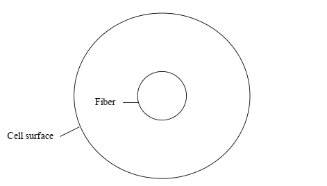
Figure 1 above shows that the cell model has a simple geometry comprising of one fiber situated in fiber in a finite space of cell surface. In this view, it is possible to account for the effects of other fibers. According to Kuwabara (1959) and Happel (1959), the cell model gives a simplified form of a real geometry and a feasible prediction. Another assumption of the cell model is that all fibers in the filter have similar flow field, which is perpendicular to the airflow orientation.
Since the cell model was the best approach employed in the resolution of fluid flow, subsequent scientists employed it for decades in elucidating of the filtration mechanism (Davies 1973; Lee & Liu 1982; Brown 1984; Brown 1993). Through the application of the cell model, Kuwabara (1959) generated the velocity profile of fiber and managed to solve equations of two-dimensional viscous flow. In the cell model, the resolution of the biharmonic equation that occurs in cylindrical polar coordinate provides the stream function (ψ) as shown below.
ψ = (Ar +B/p+ Crlnr + Dr3) sinθ. Equation (2.18)
In which A, B, C, D represent constants that indicate conditions of the boundary. Based on the assumption that the particle moves on the same path, it is possible to predict the interception efficiency. Essentially, the ratio between the limiting streamlines and the diameter of the fiber is the interception efficiency as indicated in figure 2 below.
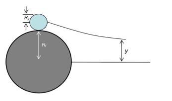
At any position on the cell, the stream function is equal to vy (ψ =vy), and thus, substitution of ????R =y/Rf generates the interception efficiency.
ER = 1+R/2Ku [2ln (1+R) -1 + (1/1+R)2 (1-α/2 ) – α/2 (1 + R)2] Equation 2.19)
In which R =RP/Rf is the constant that represents a dimensionless number known as interception parameter, Ku represents Kuwabara number (Ku =− lnα − 0.75 +α − 0.25α 2), and α shows solid volume fraction. As this equation is complex, Lee and Liu (1982) formed a simplified equation using equivalent series.
![]()
Owing to the complexity of the shape of the fibrous media, the addition of an empirical coefficient of 0.6 is necessary to validate the formula.
ER = 0.6*1-α/Ku*R2/??? Equation (2.21)
By considering the slip effect, Liu and Rubow (1990) multiplied by the equation with Cr, which is a function of kn.
![]()
Brownian Diffusion
Since Brownian motion explains why particles deviate from their streamlines during motion, the coefficient of diffusion offers an accurate quantification method. Einstein provided an equation that determines a mean displacement of a particle from one location to another.
D =σCcT/(3πμdp) Equation (2.23)
Where Cc is the slip correction factor derived by Cunningham empirically (Cc = 1 + Knp (1.257 + 0.4e-1.1/Knp) that occurs on the surface of nanoparticles, σis the Boltzmann constant (σ=1,3810-23 (m2kgs-2K-1), μ is the viscosity, T is the air temperature, and dp the particle diameter. The Eulerian approach offers a sufficient resolution of filter efficiency based on the convective-diffusive equation.
μ*δN/δx+ v*δN/δy+ w*δN/δz= D ( δ²N/δx² + δ²N/δy² + δ²N/δz²) Equation (2.24)
Over time, varied scientists have employed different equations in calculating the diffusion efficiency. Natanson (1957) came up with the formula, although it does not give an appropriate approximation because it ignores the effects of other adjacent fibers. In their study, Stechkina and Fuchs (1966) established a method that allows determination of the boundary layer analysis and applies for Peclet numbers that are greater than (Pe>100. Although this method does not provide for neighboring fibers, it simplifies effects of other adjacent fibers by considering the assumption of the cell model. Furthermore, Lee and Liu (1982) employed the Eulerian approach to formulating the convective-diffusive equation, which determines the concentration of the particles.
![]() +
+![]() *
*![]() + D*
+ D*![]() Equation (2.25)
Equation (2.25)
By ignoring the last term, including the factor of 1-α in the numerator, and adding the hydrodynamic factor (σ= (1 – ????)/Ku) improves the resolution of the above equation because it applies to a broader range of solid volume fraction. Ultimately, Lee and Liu (1982a) recommended the following theoretical solution.
ED = 2.6 (1-α/Ku1/3 Pe-2/3 Equation (2.26)
Where Pe represents the Peclet (Pe = Udf/D.
Since the equation does not fit the experiment, the insertion of a different coefficient is necessary. Lee and Liu (1982) assessed total efficiency by ignoring the effects of inertial impaction efficiency of most particles in the range of penetrating sizes. Comparison of the diffusion formula and the interception formula and their addition to variable coefficients generates a new empirical formula. The use of Etot (EtotPeR) as a new parameter instead of the old parameter (1+R) applies when the interception value is greater than 3, and total efficiency effects attributed to diffusion is less than 0.3. Therefore, Lee and Liu (1982) suggested the following equation for diffusion.
ED = 1.6 (1-α/Ku1/3 Pe-2/3 Equation (2.27)
The practical outcome generated by the above equation to alter analytical expressions emanates from SVFs of 0.151, 0.0474, and 0.0086, and a fiber diameter of 11μm assessed from nanofibers employed in the study. Comparatively, a model without a slip boundary condition is not appropriate because it undervalues the nanofibers’ diffusion efficiency. The equation formulated by Liu and Rubow (1990) is relevant because it uses the slip correction factor to account for slip boundary; however, not applicable to fibers with diameters less than 100nm. Hence, Liu and Rubow (1990) recommended the equation below.
ED = 1.6 (1-α/Ku1/3 Pe-2/3 CdCd = 1+ 0.388 Knf (1-αPe/Ku1/3 Equation (2.28)
Rao and Faghri (1988) recommended the application of numerical methods because it excludes the difficulty of separating combined effects of interception and diffusion, eliminates their effects on total efficiency, and improves the capacity to analyze these effects independently. In the analysis of effects from other fibers, the assumption of a staggered or in-line tube bank model that has two dimensions holds. Numerical resolution of the Navier-Stokes equations based on the finite volume method is the first step (Patankar 1980) followed by the Eulerian approach (equation 1.19). Comparison of the outcomes with those of Stechkina and Fuchs (1966), Kuwabara (1959), and Lee and Liu (1982) were performed for R less than 0.5.
Peclet numbers give rise to two formulas, one formula for Pe values between 100 and 300, and another formula for Pe values less than 50.
Inertial Impaction
The existence of inertia makes particles experience inertial impaction that deviate them from streamlines. The application of drag force on a particle in motion gives the following equation.
m*dv/dt= -3πμdpv Equation (2.29)
In the calculation of the first order differential equation, the following equation shows that ts is the stopping time, e is the duration needed for for velocity to decline, and ds is stopping distance.
ts =![]() and ds =
and ds =![]() Equation (2.30)
Equation (2.30)
The non-dimensional Stokes number (Stk) elucidates the influence of inertial impaction. The substitution of μ with v in the above equation gives the parameter that describes the motion of a particle. To get ds, a non-dimensional number, division by the fiber diameter generates the following equation.
Stk = ![]() Equation (2.31)
Equation (2.31)
Normally, classification of the inertial impaction comprises of can be low, medium, and high depending on Stokes numbers. The following equation allows the determination of the single-fiber efficiency of particles with low Stokes number.
EI = ![]() ; where J = (29.6) -28
; where J = (29.6) -28
![]() Equation (2.32)
Equation (2.32)
When the Stokes number is high, the velocity of particles is constant, and the streamlines are straight. The modification of equation of inertial impaction by replacing v with v-u eases resolution and forms the first order perturbation theory. Ultimately, in the instance of a high Stokes number, the following equation calculates the inertial impaction
EI = 1 -u/Stk Equation (2.33)
Where μ is the constant (μ = 0.805) that applies for SVF of 5% based on Kuwabara field. In the instance of medium Stokes numbers, the following equation of curve fitting applies.
EI = ![]() Equation (2.34)
Equation (2.34)
Reference List
Acheson, DJ 1990, Elementary fluid dynamics, Oxford University Press, New York, NY.
Agranovski, E, 1995, ‘Filtration of ultra-small particles on fibrous filters,’ PhD Thesis, Griffith University, Nathan, Australia.
Agranovski, IE & Shapiro, M 2001, ‘Clogging of wet filters by dust particles’, Journal of Aerosol Science, vol. 32, no. 8, pp. 1009-1020.
Allen, MD & Raabe, OG 1982, ‘Re-evaluation of Millikan’s oil drop data for the motion of small particles in air’, Journal of Aerosol Science, vol. 6, no. 1, pp. 537-547.
Binnig, J, Bredin, A, Meyer, J & Kasper, G 2011, ‘Dimensional analysis of the cleaning pulse intensity in a surface filter test rig’, Powder Technology, vol. 211, no. 2, pp. 275-279.
Bredin, A & Mullins, BJ 2012, ‘Influence of flow-interruption on filter performance during the filtration of liquid aerosols by fibrous filters’, Separation and Purification Technology, vol. 90, no. 1, pp. 53-63.
Bredin, A 2012, ‘The Influence of contaminant particles and filtration regime on fibrous mist-filter performance,’ PhD Thesis, Curtin University, Perth.
Bredin, A, Larcher, AV & Mullins, BJ 2011, ‘Thermogravimetric analysis of carbon black and engine soot: towards a more robust oil analysis method’, Tribology International, vol. 44, no. 1, pp. 1642-1650.
Brown, RC 1984, ‘Many-fiber model of airflow through a fibrous filter’, Journal of Aerosol Science, vol. 15, no. 1, pp. 583-593.
Brown, RC 1993, Air Filtration, Pergamon Press, London.
Brown, RC 1993, Air filtration: an integrated approach to the theory and applications of fibrous filters, Pergamon Press, London.
Castrol 2018, Material safety data sheet for castrol RX super 15W-40. Web.
Contal, P, Simao, J, Thomas, D, Frising, F, Callé, S, Appert-Collin, JC & Bémer, D 2004, ‘Clogging of fiber filters by submicron droplets. phenomena and influence of operating conditions’, Journal of Aerosol Science, vol. 35, no. 2, pp. 263-278.
Davidson, PA 2004, Turbulence: an introduction for scientists and engineers, Oxford University Press, London.
Davies, CN 1973, Air Filtration, Academic Press, London.
Daz, RV & Dominguez, ER, 2009, ‘Health risk by inhalation of pm 2.5 in the metropolitan zone of the city of Mexico’, Ecotoxicology and Environmental Safety, vol. 72, no. 3, pp. 866-871.
Flagan, RC & Seinfeld, JH 1988, Fundamentals of air pollution engineering, Prentice Hall, New York, NY.
Cheremisinoff, PN 1993, Air pollution control and design for industry. Marcel Dekker, New York, NY.
Fuchs, NA, 1964, The mechanics of aerosols. Pergamon Press, London.
Gentry, JW & Spurny, KR 1978, ‘Measurements of collection efficiency of nuclepore filters for asbestos fibers’, Journal of Colloid and Interface Science, vol. 65, no. 1, pp. 174-180.
Gushchin, VA, Kostomarov, AV, Matyushin, PV & Pavlyukova, ER 2002, ‘Direct numerical simulation of the transitional separated fluid flows around a sphere and a circular cylinder’, Journal of Wind Engineering and Industrial Aerodynamics, vol. 90, no. 4, pp. 341-358.
Happel, J 1959, ‘Viscous flow relative to arrays of cylinders’, AIChE Journal, vol. 5, no. 2, pp. 174-177.
Hilpert, M 2010, ‘Effects of dynamic contact angle on liquid withdrawal from capillary tubes: (semi)-analytical solutions’, Journal of Colloid and Interface Science, vol. 347, no. 2, pp. 315-323.
Hinds, WC 1999, Aerosol technology, John Wiley & Sons, New York, NY.
Hosseini, SA 2011, ‘Modelling particle filtration and cracking in fibrous filter media,’ PhD Thesis, Virginia Commonwealth University, Richmond.
Jaganathan, S, Tafreshi, HV & Pourdeyhimi, B 2009, ‘A realistic modeling of fluid infiltration in thin fibrous sheets’, Journal of Applied Physics, vol. 105, no. 11, pp. 1-8.
Jakab, E & Omastova, M 2005, ‘Thermal decomposition of polyolefin/carbon black composites’, Journal of Analytical and Applied Pyrolysis, vol. 74, no. 2, pp. 204-214.
Kasper, G, Schollmeier, I, Meyer, J & Hoferer, J., 2009, ‘The collection efficiency of a particle-loaded single filter fiber’, Journal of Aerosol Science, vol. 40, no. 1, pp. 993-1009.
Kuwabara, S 1959, ‘The forces experienced by randomly distributed parallel circular cylinders of spheres in a viscous flow at small Reynolds number’, Journal of the Physical Society of Japan, vol. 14, no. 4, pp. 527-532.
Lee, KW & Liu, BYH 1982, ‘Theoretical study of aerosol filtration by fibrous filters’, Aerosol Science and Technology, vol. 1, no. 1, pp. 147-161.
Li, SQ & Marshall, JS 2007, ‘Discrete element simulation of micro-particle deposition on a cylindrical fiber in an array’, Journal of Aerosol Science, vol. 38, no.10, pp. 1031-1046.
Liu, BYH & Rubow, KL 1990, ‘Efficiency, pressure drop and figure of merit of high efficiency fibrous and membrane filter media’, Proceedings of the Fifth World Filtration Congress, Nice, pp. 5-8.
Loffler, F 1988, Staubabscheiden, Georg Thieme Verlag, Stuttgart, Germany.
Manton, MJ 1967, ‘The impaction of aerosols on a nuclepore filter’, Atmospheric Environment, vol. 12, no. 8, pp. 1669-1675.
Myojo, T, Kanaoka, C & Emi, H 1984, ‘Experimental observation of collection efficiency of a dust-loaded fiber’, Journal of Aerosol Science, vol. 15, no. 1, pp. 483-489.
Patankar, SV 1980, Numerical heat transfer and fluid flow, Hemisphere Publisher, Washington, WA.
Peukert, W 1998, ‘High temperature filtration in the process industry’, Filtration and Separation, vol. 35, no. 5, pp. 461-464.
Pohanish, R 2002, Sittig’s handbook of toxic and hazardous substances and carcinogens, Wlliam Andrew Publishing, New York, NY.
Polichetti, G, Cocco, S, Spinali, A, Trimarco, V & Nunziata, A 2009, ‘Effects of particulate matter (pm10, pm2.5 and pm1) on the cardiovascular system’, Toxicology, vol. 261, no. 1, pp. 1-8.
Rao, N & Faghri, M 1988, ‘Computer modeling of aerosol filtration by fibrous filters’, Aerosol Science and Technology, vol. 8, no. 2, pp. 133-56.
Raynor, PC & Leith, D 2000, ‘The influence of accumulated liquid on fibrous filter performance’, Journal of Aerosol Science, vol. 31, no. 1, pp. 19-34.
Raynor, PC 2008, ‘Single-fiber interception efficiency for elliptical fibers’, Aerosol Science and Technology, vol. 42, no.1, pp. 357-368.
Ruiz, JC, Blanc, P, Prouzet, E, Coryn, P, Laffont, P & Larbot, A 2000, ‘Solid aerosol removal using ceramic filters’, Separation and Purification Technology, vol. 19, no. 3, pp. 221-227.
Schlichting, H 1979, Boundary-layer theory, Springer, Berlin, Germany.
Shahad, HAK 1989, ‘An experimental investigation of soot particle size inside the combustion chamber of a diesel engine’, Energy Conversion and Management, vol. 22, no. 2, pp. 141-149.
Stratakis, GA & Stamatelos, AM 2003, ‘Thermogravimetric analysis of soot emitted by a modern diesel engine run on catalyst-doped fuel’, Combustion and Flame, vol. 132, no. 2, pp. 157-169.
Theodore, L & Buonicore, AJ 1988, Air pollution control equipment, CRC Press, New York, NY.
Tien, C. 1989, Granular filtration of aerosols and hydrosols, Butterworth, Boston, MA.
Versteeg, HK & Malalasekera, W 2007, An introduction to computational fluid dynamics: the finite volume method, Prentice Hall, New York, NY.
Wang, J, Kim, SC & Pui, DY 2008, ‘Investigation of the figure of merit for filters with a single nanofiber layer on a substrate’, Journal of Aerosol Science, vol. 39, no. 4, pp. 323-334.
Zhao, S & Povitsky, A 2009, ‘Method of fundamental solutions for partial-slip fibrous filtration flows’, International Journal for Numerical Methods in Fluids, vol. 61, no. 3, pp. 255-274.