Introduction
A thorough understanding of the laws of electrical circuits ensures the success of academic study of this section of physics and the ability to use the knowledge in practice effectively. This laboratory work evaluated the applicability of Ohm’s electrical law to the circuit being generated. In particular, it was shown how to create schemes using interactive tools and to measure key electrical metrics in them using the built-in functionality and calculations. The approach of modifying circuits depending on the resistance value of resistors and the voltage of the DC Power Source was utilized to verify the electrophysical law. The purpose of this laboratory report was to determine the relevance of applying Ohm’s law to electrical circuits even with their modifications.
Procedure
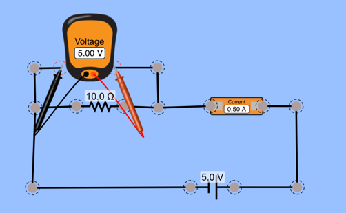
The guidelines for this laboratory work were used as a guideline. In particular, using the tool of interactive creation of electric schemes, the circuit was generated such as the one illustrated in the instructions (“Circuit construction kit AC prototype,” n.d.). A screenshot of the primary circuit generated is shown in Figure 1. It was created using virtual wires, one resistor, a voltage source, an ammeter, and a voltmeter connected in parallel to the main scheme.
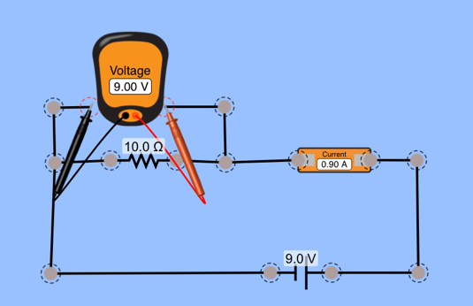
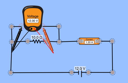
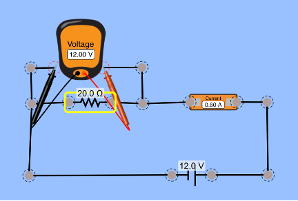
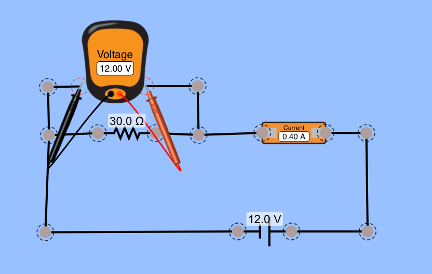
Subsequently, the circuit was subjected to modifications in order to evaluate the possibility of applying Ohm’s law to the ratios of key electrical metrics: resistance, voltage, current. More specifically, this involved adding three resistors with three different resistances in series to the circuit (Table 1), increasing the DC Power Source voltage, and changing the voltage of the resistors (Table 2). Schematic representations of each of the modified circuits are shown below. For each of the cases considered, the necessary circuit parameters were measured, and calculations were made.
Data Observation
Data Table 1
DC Power Source: 12.0 V
Data Table 2
Resistance: 10.0 Ω
Data Analysis and Calculations
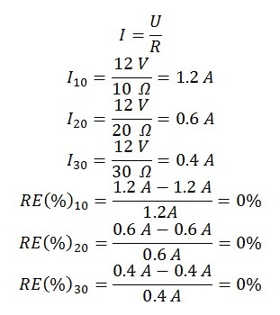
Since the voltage of the circuit in Table 1 did not change, but the resistor resistance value did, it is correct to expect that the current flowing through the wires will be affected by this. Specifically, the mathematical formulation of Ohm’s law given in equation [1] is used to calculate current values. Given the inverse proportionality between current and resistance, it was shown that the greater the resistance the resistor had, the less current would flow through the circuit. Additionally, it is worth noting that the data obtained agreed well with the numbers shown in Figures 2-4, and hence the percentage of error was zero in all cases [2.1]-[2.3]. Based on the obtained data, it can be concluded that there was no discrepancy between the calculated and measured current values for the electric circuit. In turn, this indicates a high reliability of the data.
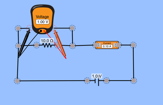
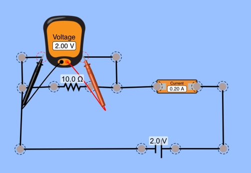
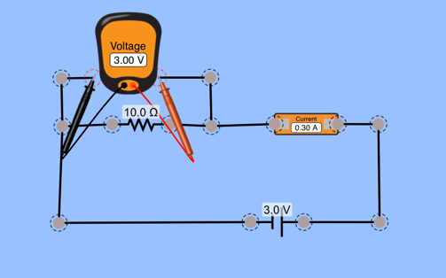
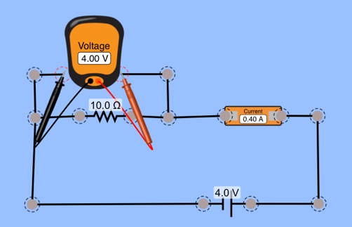
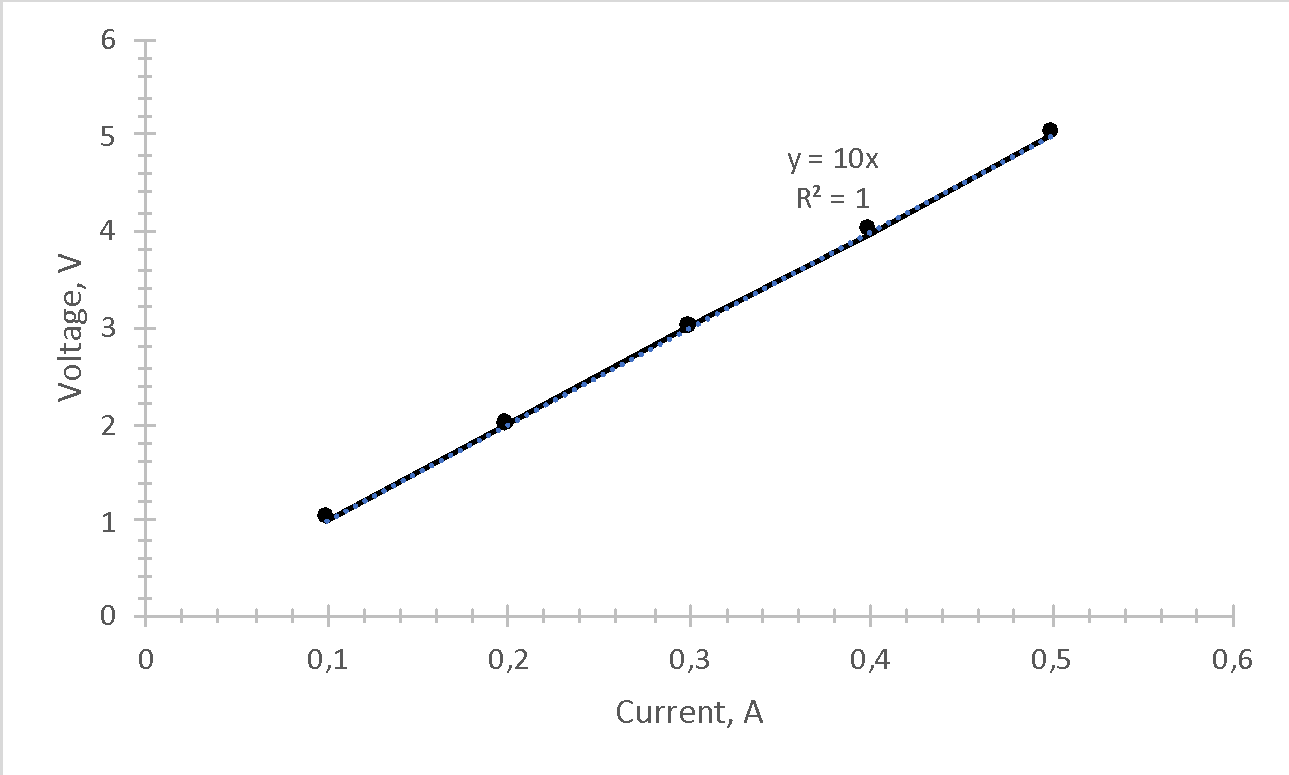
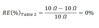
For Table 2, the approach of sequentially increasing the DC Power Source voltage from 1 V to 5 V in a circuit with a resistor whose resistance was always 10 Ω was used. The purpose of this examination was to relate the set value of the resistance to what could be calculated graphically from the equation [1]. Therefore, the measured current values as a function of the DC Power Source voltage are shown in Table 2. Based on the first two columns, in MS Excel, a curve was plotted in the coordinates “Voltage” and “Current,” an illustration of which is shown in Figure 10. It was additionally noted that the slope of this linear function was strictly 10, which was entered in Table 2. Considering that the calculated resistance value was equal to the set value, the error percentage was zero [3.1].
Conclusion
Considering all of the above, it is appropriate to state that the calculations performed correlated perfectly with those measured using the interactive model. In particular, the deliberate use of electrical circuits allows the practical use of the knowledge gained and the finding of patterns. The work showed that Ohm’s law was applicable for each of the nine circuits created. Moreover, the calculated indirect data of key metrics were entirely consistent with expectations, which means that using Ohm’s Law for any circuit regardless of resistance or voltage values is appropriate.
Reference
Circuit construction kit AC prototype. (n.d.). PHET. Web.